AcSample Prototype
May 2025 - August 2025

One of my major projects during my first summer as a Mechanical Engineering intern at Acbotics was early prototyping for their in vitro eDNA sampling systems, later named the AcSample. When I first arrived, they had some of the higher-level design choices planned out (i.e. they had selected particular peristaltic pumps to try out, had chosen the type of flow sensor and tubing that they wanted to use, had some PVC pipes and fixtures on hand), but still had yet to fit everything into housings and make it something that could easily be deployed into the water off the back of a boat or dock. They were also deciding if they wanted to make two different prototype sizes (with different pumping capabilities) to see which size was preferred by customers (or if both had their niches).
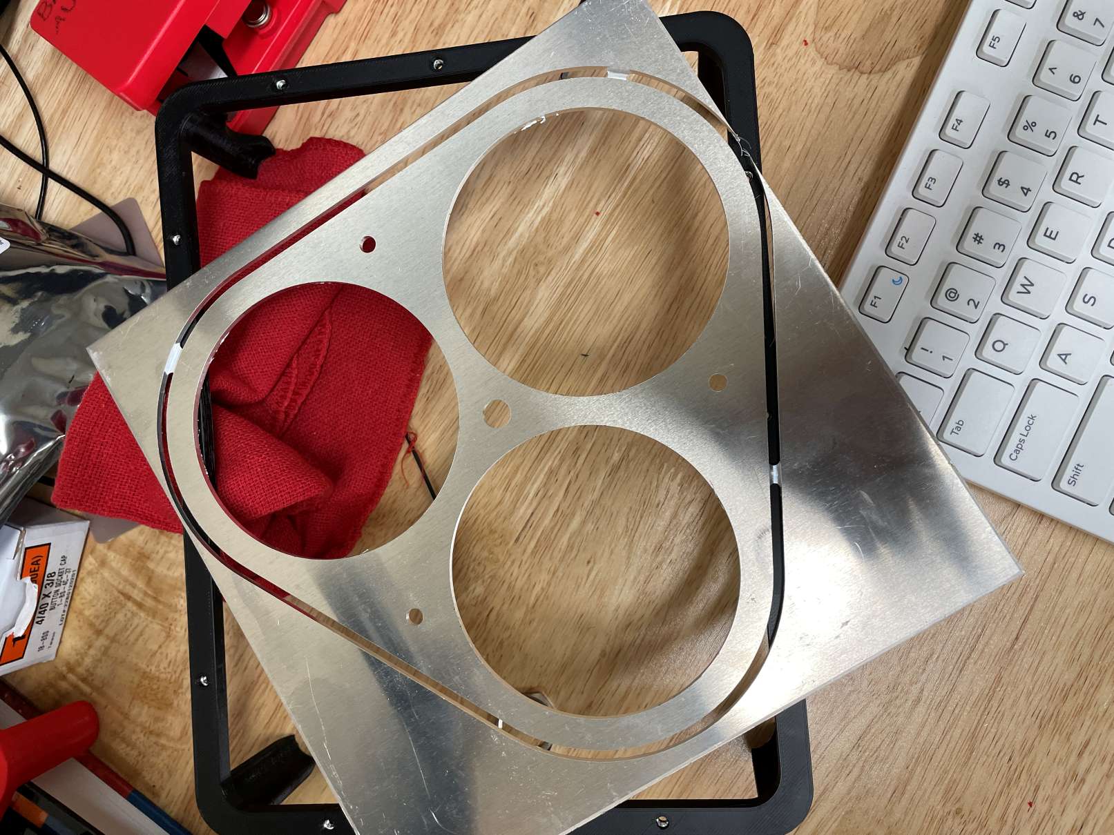
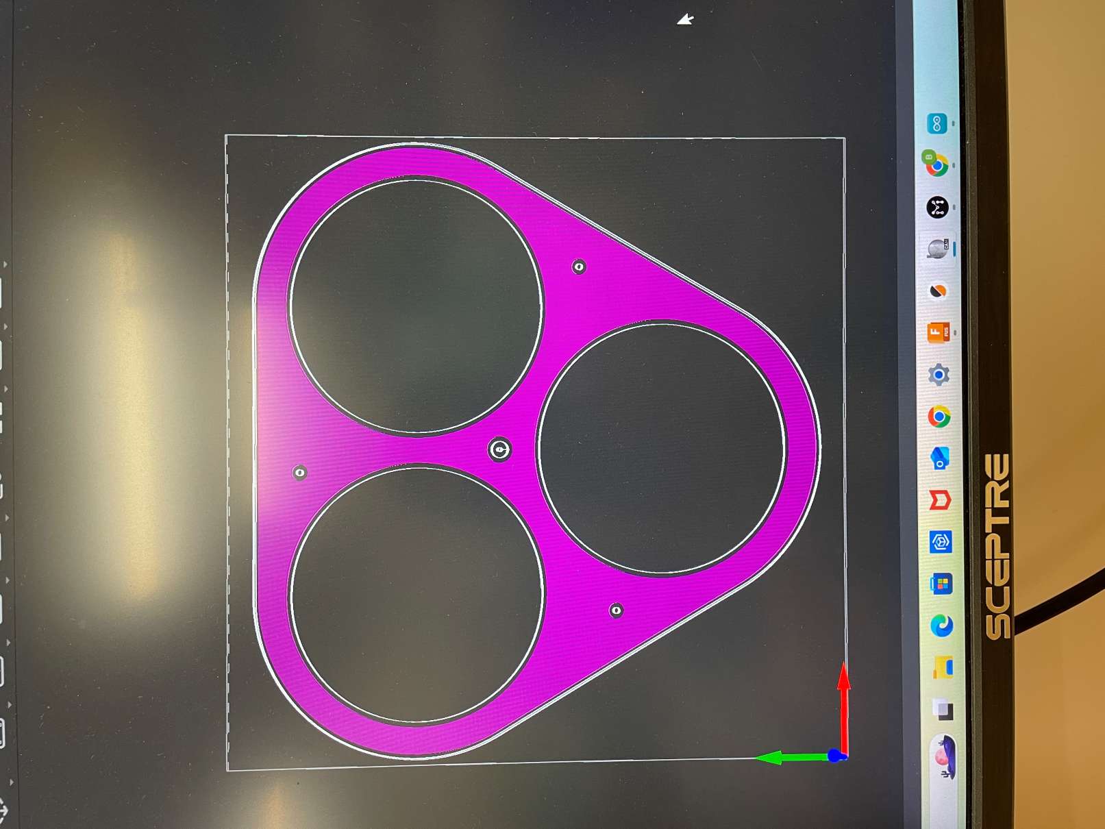
Since the pump system itself and the electronics were going to be housed separately, my first task was to design some sort of outer framing that would connect these PVC housings without being too cumbersome and avoid any tangling of cables. Since each housing was quite heavy, it would be difficult to use 3D-printed parts (especially out of PLA/PETG, which was the main filament we had on hand) that could reliably hold everything together without chipping or snapping. However, I had access to a desktop CNC machine (a Carvera Air) which I had previously used for the PLUTOS Source Box. Although I had only cut acrylic with it before, it was designed to cut into soft metals quite easily, so I decided to make my mounting design an aluminum plate. I made my design in Fusion, then ported it over to the supplied software that came with the CNC machine, MakeraCAM. The software was quite simple (primarily made for 2D contours and basic toolpaths), but was quick and easy to use. The main constraint was space, since the bed size was only 300mm x 200mm.
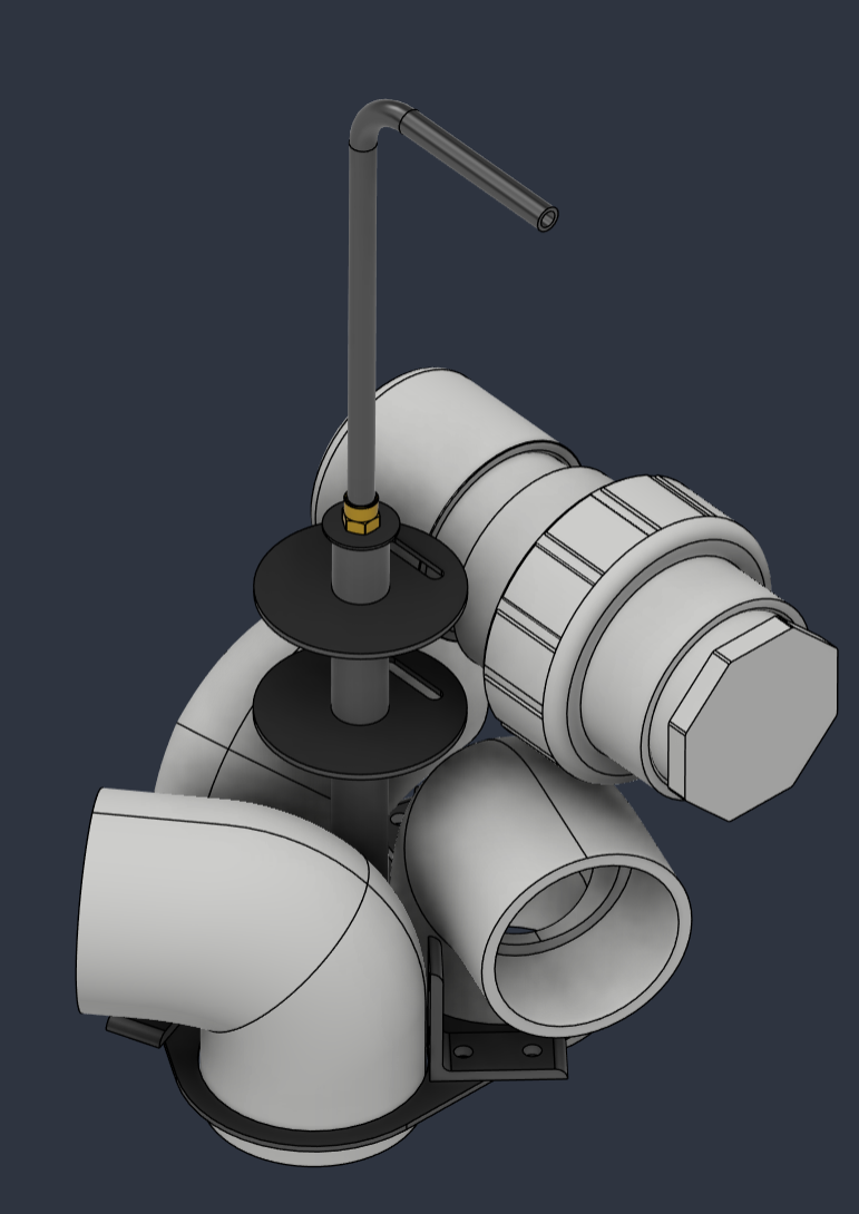
The plate was easy to cut, and the rest of the assembly came together quickly. I left one hole in the center that I mounted a thin steel pipe to, which became the carrying handle for the whole assembly. Small L-pieces were mounted next to each hole for the PVC pipes and provided a tab for metal pipe clamps to be secured around each pump housing. Two metal discs were then installed higher-up on the main shaft of the handle, which had slots cut in them so the electronics housing could be attached. Although the full assembly was large (when placed on the ground, the handle was around waist-high), it was balanced enough to be easy to dip into the water.
After making the larger prototype, I also made a mounting bracket for the smaller design. The manufacturing process was nearly identical, except that I used Fusion CAM instead of the software provided with the machine. It took some time to get all of the settings configured in Fusion, but Fusion provides a lot more options for toolpaths and was a much more practical option long-term for Acbotics. Since there was no longer a flat, level surface for the assembly to sit on, I added a couple of threaded rods to the side with the electronics housing. This is the assembly at the top of this section.
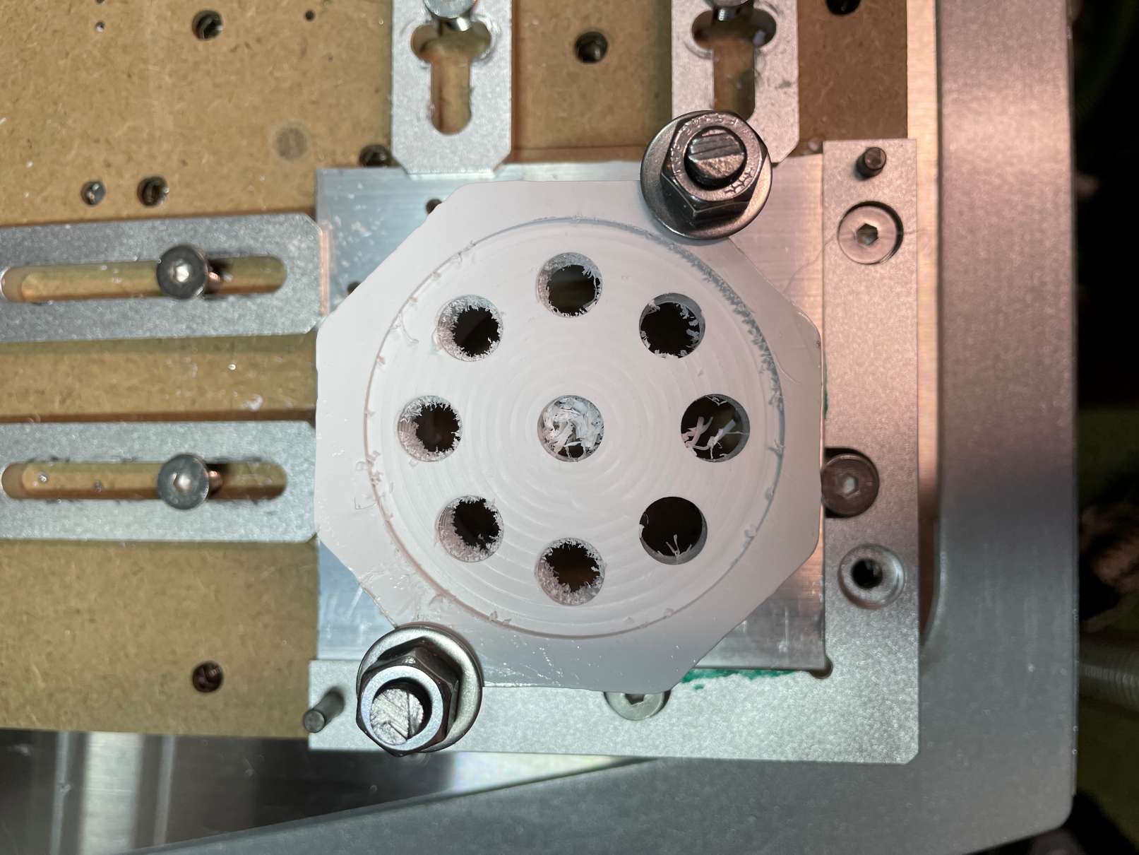
Finally, after designing these two prototypes, I was tasked with making a fixture for the desktop CNC machine that would allow us to more easily machine holes into the PVC caps. Prior to making this fixture, we had been measuring and drilling holes by hand (and using the drill press), which was time-consuming and inconsistent. I made a simple design consisting of a bottom plate and two clamps, and created a generic CAM file with the fixture modeled in (so toolpaths would automatically avoid the fixture or throw errors). After the first few caps were successful, I made two more fixtures for different plug sizes. The holes drilled in these plugs were inlet/outlet ports for each pump or bulkheads for other cables.
AcSample Production
January 2026, May 2026 - August 2026
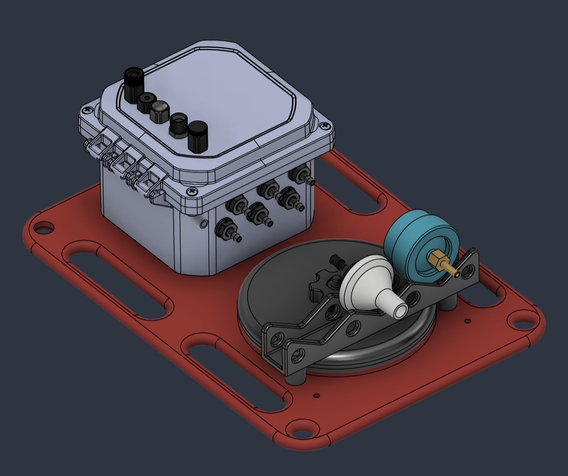
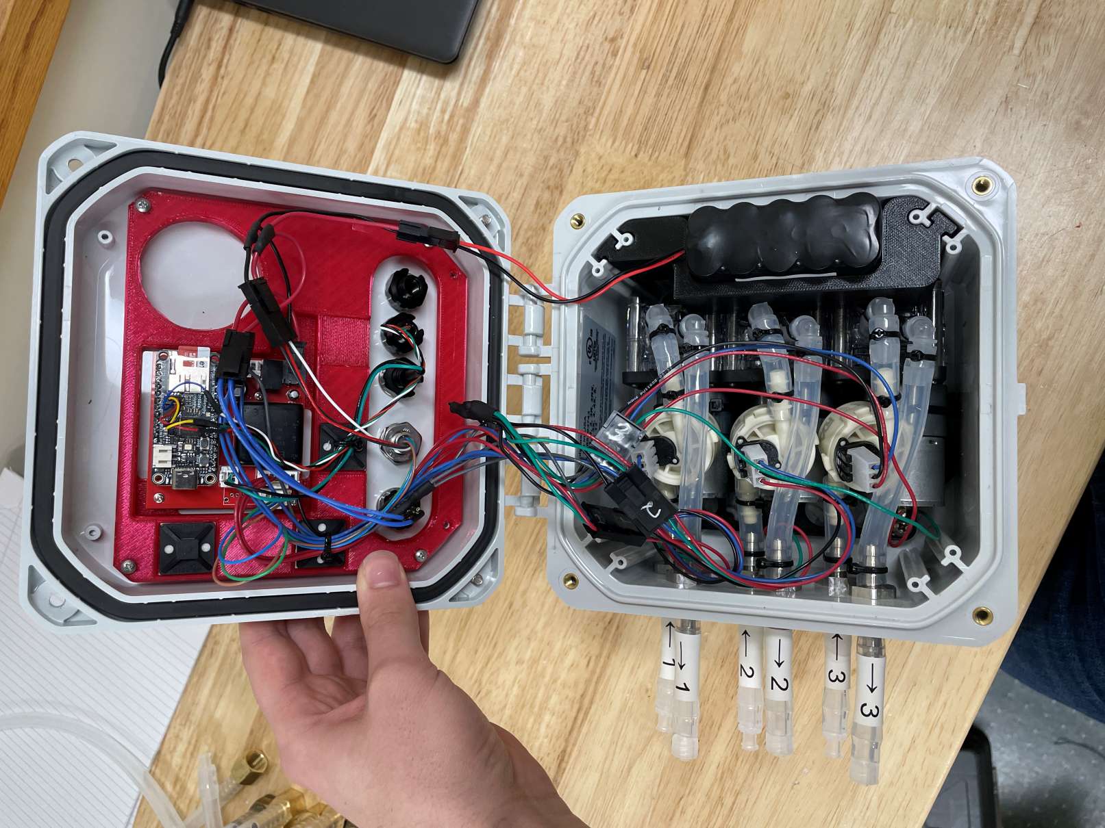
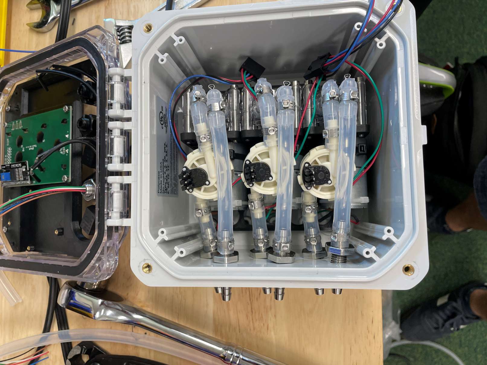
In the time between my previous summer internship and my winter project support, the rest of the Acbotics team used the feedback from the early AcSample prototypes to design their first pre-production model. During the winter, I helped to make a few modifications to the current pre-production design, wrote assembly instructions for that model, and built up around eight units. Instead of having separate housings for the pumps and electronics like in previous models, everything was condensed down to fit into a single case. To make it easier to connect external filters while still sealing reliably, luer lock fittings were used. My thorough instructions helped part-time team members who were less familiar with the project easily assemble more units the following spring.
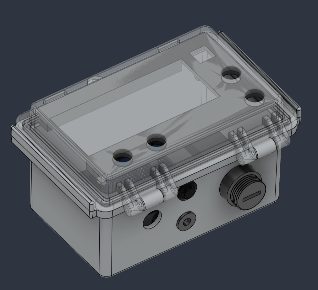
When I returned in the summer of 2026, I was largely able to pick up where I left off. Based on further testing, customers wanted to have a display which would make the AcSample easier to program and understand without relying on a single blinking LED. So, I helped to design a new lid print which could fit the new screen, wider electrical board, and still leave enough room to tighten and adjust the bulkheads. Since we also had a better idea of the customization options that customers wanted, I helped to design the different main options that would be sold to customers, including two units designed to be mounted above water, one unit for 5 meters of depth, another for 20 meters depth, and an oil-filled variant for 100 meters depth. These units varied in which switches were used and how the internal flow sensors were secured so that customers only paid for the features they needed.
In addition to the new models, I also designed accompanying manager and battery boxes, which would connect to AcSample units with a cable for charging, programming, and data download. For the manager box, an LED screen was mounted to the clear lid, and four buttons were used to navigate through the menus. For the battery box, I designed a slotted lid which allowed the battery to be rigidly secured regardless of orientation.
For all of these products, I re-worked any previous assembly instructions that we had to make them more scalable. Rather than having a single set of instructions for the entire AcSample-Vis, for example, I broke the product down into 3-4 levels of subassemblies that could be stocked and wrote individual instructions for each subassembly. I also used Inventree to move our previous Bill of Materials (BOM) into a full inventory system, and linked all of the documentation and fabrication files for each part.
While working on this project, I also recommended that the team invest in a new printer to handle the volume of 3D-printed parts needed for the AcSample family of products. We had been using a Prusa MK3S for all of the prototyping and smaller projects, but it was clear that we would need a more modern printer. I made a small presentation that compared options (primarily Bambu printers), and we decided that an X2D with an automatic material switcher (AMS) was the most cost-effective option. I set up the printer, created a guide on how to use the Bambu Slicer and X2D itself, and helped to claim warranty on the broken screen it arrived with. The new printer was roughly twice as fast, could print dedicated support material on the second nozzle, and the AMS meant the printer had less downtime with switching filaments. The AMS also doubled as a filament dryer for the PETG we used, and the addition of the X2D greatly improved our printing uptime. With the new printer, I was also able to print an IP-67 test enclosure out of ABS, and showed that the X2D could be useful for other projects requiring water-resistant housings without needing a dedicated electronics box. Overall, I became a lot more comfortable with FDM printing and have come to appreciate how useful it is for prototyping.
PLUTOS Source Box
May 2025 - August 2025
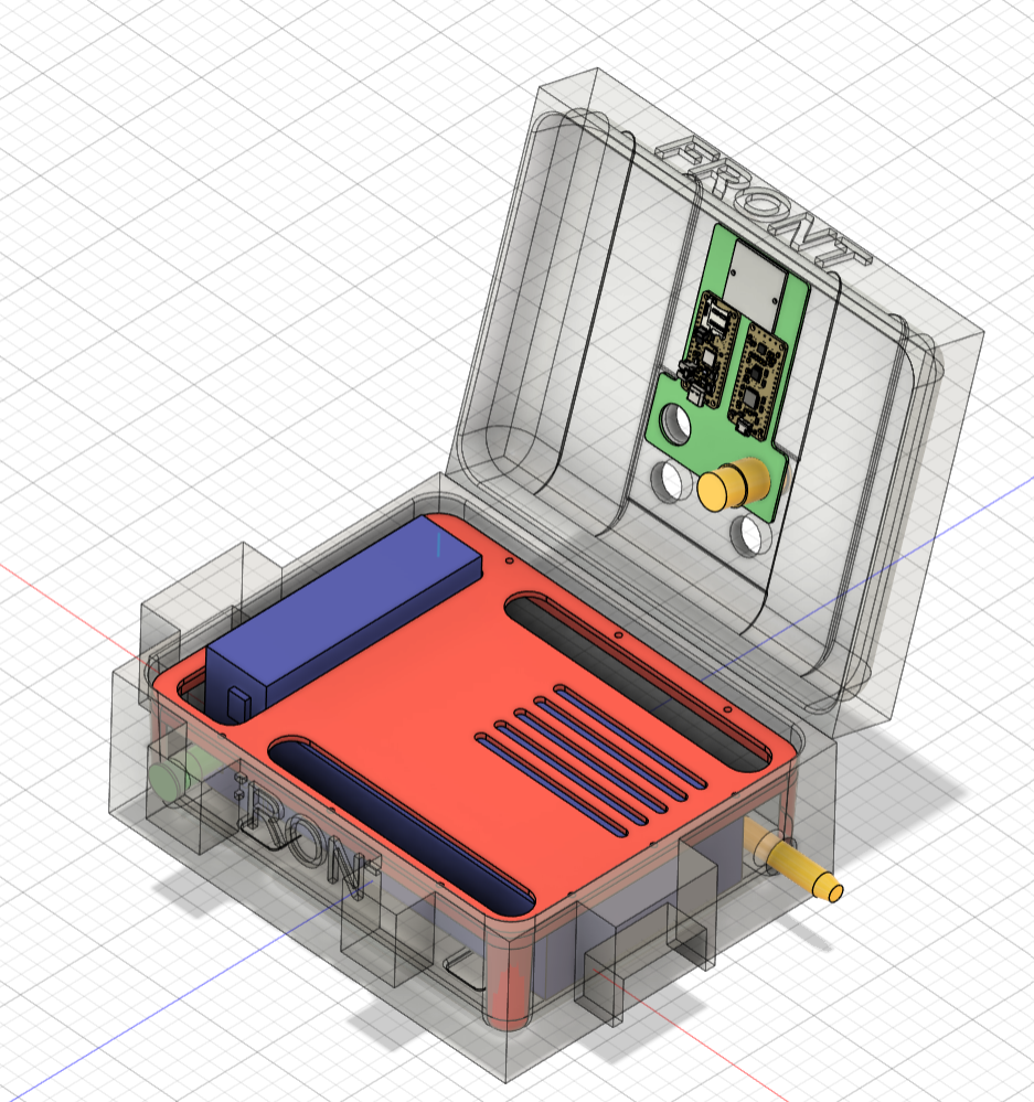
My very first project that I worked on at Acbotics was a sound source box designed to play seal calls underwater. I was tasked with finding a way to mount all of the internals needed in the case (large amplifier, battery, GPS, buttons, etc.) so that none of the smaller components got damaged by the heavier items. The goal was to make four of these units and make them easy to deploy from kayaks for an experiment in August with students from Portland State University and the University of Delaware.
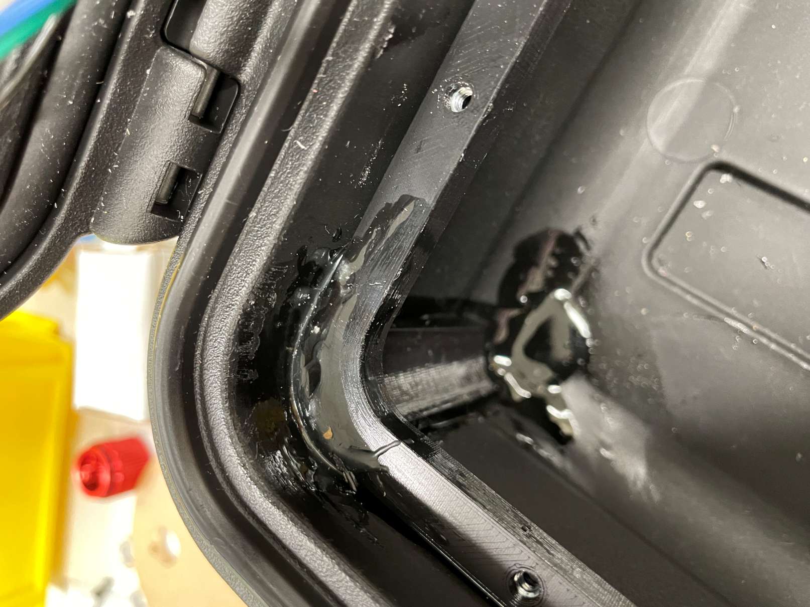
In my design, I decided to 3D-print a bezel with square nuts embedded into the print, and epoxied that bezel directly to the base of the case. Since the walls were thin and there were no internal mounting holes, the only other option would have been to drill through the case and seal each hole, which seemed more unreliable. Although the epoxy was messy to apply, it was easy to clean up before setting and provided the strength needed to hold components in place with the case at any angle.
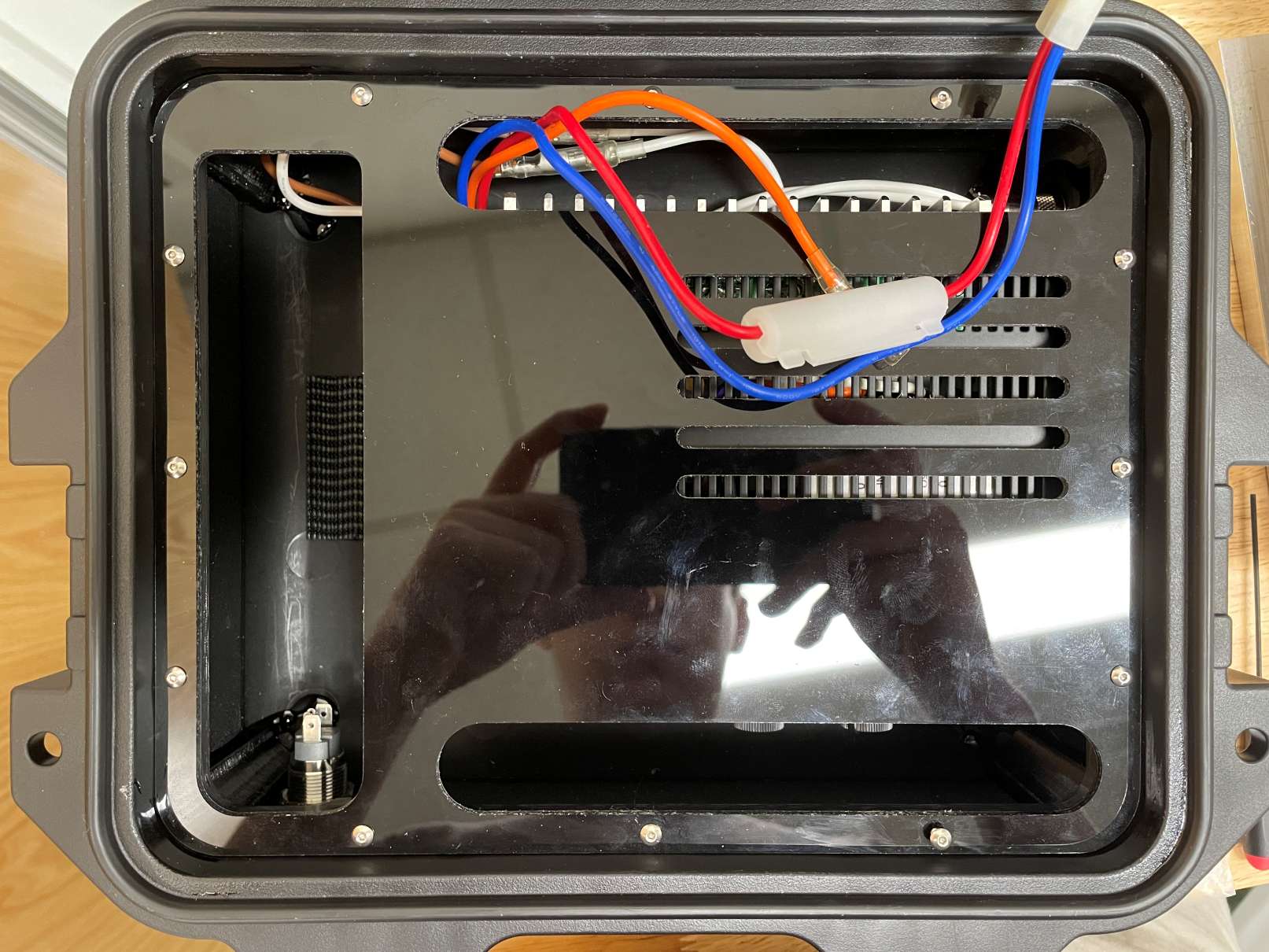
I then used a desktop CNC machine (a Carvera Air) to machine an acrylic lid that attached to the bezel. The office had acquired the machine just a couple of weeks before my internship started, and while they had run some test files on it they had yet to use it for an actual project. I familiarized myself with the software and cut a few different versions of the lid as I iterated over the design. I was really happy with how sleek and clean the design looked!
The source box also had an internal mount for the electronics which I designed, as well as several holes around the case for buttons, the connection to the speaker itself (which would be deployed under the water), and a power button. Once the first box passed testing, I built up three more.
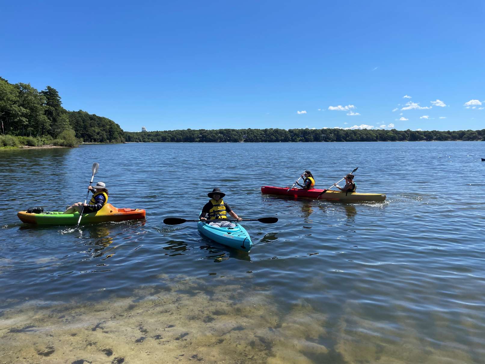
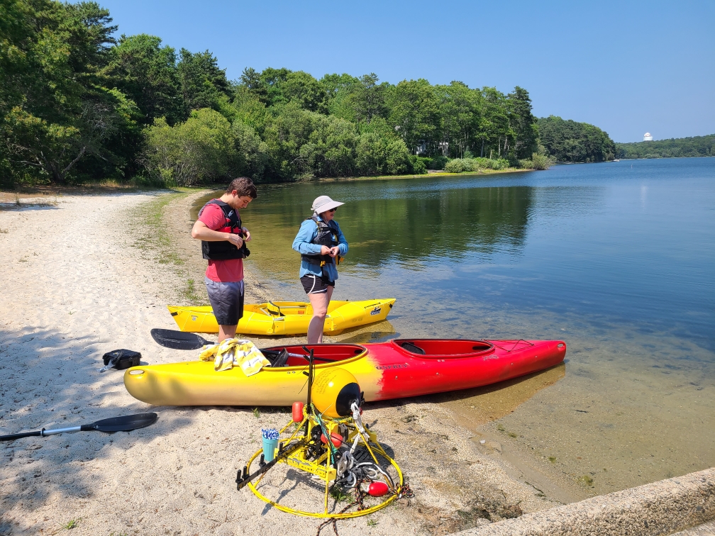
For a week in August, I got to help run the experiment (“PLUTOS”) that my source boxes were being used in, where our goal was to obtain some reference data for tracking seals from their calls using hydrophone arrays. At the beginning of each testing day, I helped my boss to deploy two hydrophone arrays in the middle of the pond. I then acted as the on-site “lifeguard” for our tests, since many of the incoming students were less familiar with swimming and had never been on a kayak before. Each of our four kayaks received a source box and speaker, and we used walkie-talkies to arrange ourselves into formations and choose sounds on the source boxes. Outside of a minor hiccup or two (for example, the cable penetrator used for the speaker connection had really short threads, so a couple of them came loose during the first day of testing and needed to be modified), the cases worked like a charm and got the research groups the data they needed. I had a lot of fun!